Pre Column Installation Check List
Proper column installation is essential in obtaining the highest performance and lifetime from a capillary column.
- Cool down the injector and detector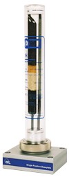
- Inspect gas filters and replace saturated traps "Click to GC - Gas filters - Filtres GC" >>>
- Check the injector and the detector, Clean or replace all dirty or corroded parts
- Change the injection Septum, the inlet liner and the injector seals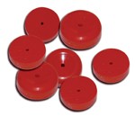
"Click to GC Injection Septa" >>>
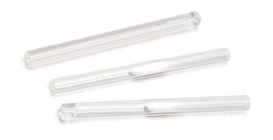 <<< "Click to Injection Liners"
- Place the nut and appropriate ferrule* on the column and carefully cut the column end (up to 10cm) using a ceramic wafer or a diamond tipped pencil or a sapphire cutting tool.
| Column Inner diameter | Ferrule Inner diameter | <<< "Click to GC- Capillary ferrules" |
| 0.10-0.18-0.20-0.25 mm | 0.4 mm | |
| 0.32 mm | 0.5 mm | |
| 0.45-0.53 mm | 0.8 mm | |
The optimal insertion distance of the column into the injector is different for each model of GC (mentioned in your instrument manual)
- Turn on the carrier gas to the flow rate or inlet pressure recommended for the column. Confirm the presence of column flow by immersing the column outlet in a vial of solvent and flush the column at ambient temperature at least 5 minutes for 25-30m column and 10 minutes for 50-60m column.
| Approximate Head Pressure (PSI) | ||||||
| 0.18mm | 0.20mm | 0.25mm | 0.32mm | 0.45mm | 0.53mm | |
| 10m | 5-10 | |||||
| 12m | 10-15 | |||||
| 15m | 8-12 | 5-10 | 1-2 | |||
| 20m | 10-20 | |||||
| 25m | 20-30 | |||||
| 30m | 15-25 | 10-20 | 3-5 | 2-4 | ||
| 40m | 20-40 | |||||
| 50m | 40-60 | |||||
| 60m | 30-45 | 20-30 | 6-10 | 4-8 | ||
| 75m | 8-14 | 5-10 | ||||
| 105m | 7-15 | |||||
- Install the column into the detector as described in the instrument manual.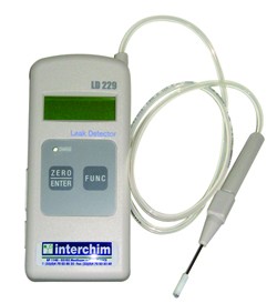
Set the detector gases and temperatures to proper settings
- Inspect for leaks all connections using a leak detector
"Click to GC-Gas filters - leak detector" >>>
- Verify the carrier gas flow, set the split vent, septum purge and any other application gas rates as appropriate
 <<< "Click to GC-Gas filters - Gas flowmeter"
- Confirm carrier gas flow and proper column installation
- Condition the column 20°C above the final analysis temperature of your method. Do not exceed the column’s maximum operating temperature
- To check for instrument performance, analyse a column test mix for a new method or a known standard to confirm proper column and system performance.
- Accurately set the carrier gas velocity (recommended average linear velocity 30 to 40 cm/sec for Helium, 50 to 80 cm/sec for Hydrogen)
Set the oven to the initial temperature of the temperature program or to the isothermal value. Inject 1-2µl of the appropriate non-retained compound. Adjust the head pressure until the desired average liner velocity is obtained.
- Bleed test : acquire a blank run (no injection) using a temperature program. Starting at 40–50°C, ramp 10-20°/min, then hold for 10-15 minutes at the conditioning temperature.
- Run test mix : Inject a test mixture to measure system performances . The test mixture is useful as a comparative and diagnostic sample.